Investigation of operational stability
Problem: Component testing to investigate the operational stability of retaining claws
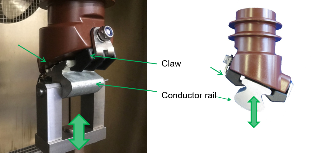
So-called retaining or holding claws made of a 30 % glass fibre reinforced polyamide 6 (PA6 GF30) are used for the operation of the Wuppertal suspension railway, which structurally fasten the conductor rail along the entire track. In order to embrace the conductor rail, the holding claws are arranged in pairs (Fig. 1). Due to assembly processes as well as the operation of the track, the retaining claws experience both static loads due to the dead weight of the rail and vibrating loads when passenger trains pass over. To ensure the operational safety of different samples of a new batch, the retaining claws are characterised with regard to their mechanical properties under static and dynamic-cyclic load. Batch checks are indicated due to regular replacement intervals.
Methodology: Quasi-static testing and fatigue tests based on field tests
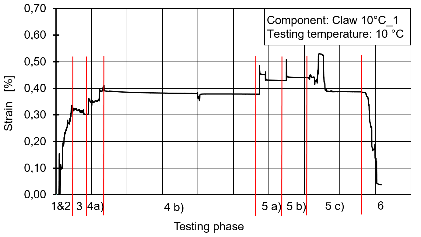
Laboratory tests (Fig. 1) are used for the experimental determination of the force/strain behaviour and the subsequent correlation with static loads in the installed state (field test) as well as the static loads in connection with installation processes, such as hooking, bending of a curved position or hammer blows (field test, see Fig. 2).
From further field tests, dynamic loads are determined that prevail when passenger trains pass over.
The average and peak loads determined from both field tests are used as input parameters for dynamic cyclic fatigue tests in the installed state and serve to check the fatigue strength.
Result: Confirmation of the fatigue strength under laboratory conditions
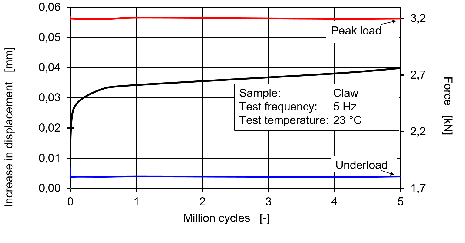

Based on the strain loads determined in field tests on the basis of assembly and overrun processes, centre loads and peak loads can be assigned for the dynamic fatigue test in correlation with the laboratory tests. Based on this, holding claws are dynamically cyclically loaded at an average of 2,500 N +/- 700 N for up to 5 million load cycles.
All examined pairs of retaining claws reach the target load cycle of 5 million load cycles without any sudden changes in properties, resulting in an estimated service life of approx. 12 years (Fig. 3). Since replacement intervals are scheduled in the maintenance plan after 10 years, the holding claws can be used according to their intended purpose.
Any questions?